Data Link Layer
The Data Link layer is split into three modes:
- Packet mode
- Data are sent in small bursts, on the order of 100s to 1000s of bytes at a time, after which the physical layer stops sending data. e.g. messages, beacons, etc.
- Stream mode
- Data are sent in a continuous stream for an indefinite amount of time, with no break in physical layer output, until the stream ends. e.g. voice data, bulk data transfers, etc.
- BERT mode
- PRBS9 is used to fill frames with a deterministic bit sequence. Frames are sent in a continuous sequence.
When the physical layer is idle (no RF being transmitted or received), the data link defaults to packet mode.
As is the convention with other networking protocols, all values are encoded in big endian byte order.
Stream Mode
In Stream Mode, an indefinite amount of payload data is sent continuously without breaks in the physical layer. The stream is broken up into parts, called frames to not confuse them with packets sent in packet mode. Frames contain payload data interleaved with frame signalling (similar to packets). Frame signalling is contained within the Link Information Channel (LICH).
Sync Burst
All frames are preceded by a 16-bit synchronization burst.
- Link setup frames shall be preceded with 0x55F7.
- Stream frames shall be preceeded with 0xFF5D.
- Packet frames shall be preceeded with 0x75FF.
- BERT frames shall be preceeded with 0xDF55.
All syncwords are type 4 bits.
These sync words are based on Barker codes.
Link setup frame
First frame of the transmission contains full LSF data. It’s called the Link Setup Frame (LSF), and is not part of any superframes.
| DST | 48 bits | Destination address - Encoded callsign or a special number (eg. a group) |
| SRC | 48 bits | Source address - Encoded callsign of the originator or a special number (eg. a group) |
| TYPE | 16 bits | Information about the incoming data stream |
| META | 112 bits | Metadata field, suitable for cryptographic metadata like IVs or single-use numbers, or non-crypto metadata like the sender’s GNSS position. |
| CRC | 16 bits | CRC for the link setup data |
| TAIL | 4 bits | Flushing bits for the convolutional encoder that do not carry any information. Only included for RF frames, not included for IP purposes. |
| Bits | Meaning |
|---|---|
| 0 | Packet/stream indicator, 0=packet, 1=stream |
| 1..2 | Data type indicator, \(01_2\) =data (D), \(10_2\) =voice (V), \(11_2\) =V+D, \(00_2\) =reserved |
| 3..4 | Encryption type, \(00_2\) =none, \(01_2\) =AES, \(10_2\) =scrambling, \(11_2\) =other/reserved |
| 5..6 | Encryption subtype (meaning of values depends on encryption type) |
| 7..10 | Channel Access Number (CAN) |
| 11..15 | Reserved (don’t care) |
The fields in Table 3 (except TAIL) form initial LSF. It contains all information needed to establish M17 link. Later in the transmission, the initial LSF is divided into 6 “chunks” and transmitted beside the payload data. This allows late-joiners to reconstruct the LICH after collecting all the pieces, and start decoding the stream even though they missed the beginning of the transmission. The process of collecting full LSF takes 6 frames or 6*40 ms = 240 ms. Four TAIL bits are needed for the convolutional coder to go back to state 0, so the ending trellis position is also known.
Voice coder rate is inferred from TYPE field, bits 1 and 2.
| Data type indicator | Voice coder rate |
|---|---|
| \(00_2\) | none/reserved |
| \(01_2\) | no voice |
| \(10_2\) | 3200 bps |
| \(11_2\) | 1600 bps |
Subsequent frames
| LICH | 48 bits | LSF chunk, one of 6 |
| FN | 16 bits | Frame number, starts from 0 and increments every frame to a max of 0x7fff where it will then wrap back to 0. High bit set indicates this frame is the last of the stream. |
| PAYLOAD | 128 bits | Payload/data, can contain arbitrary data |
| TAIL | 4 bits | Flushing bits for the convolutional encoder that don’t carry any information |
The most significant bit in the FN counter is used for transmission end signalling. When transmitting the last frame, it shall be set to 1 (one), and 0 (zero) in all other frames.
The payload is used so that earlier data in the voice stream is sent first. For mixed voice and data payloads, the voice data is stored first, then the data.
| Bits | Content |
|---|---|
| 0..39 | 40 bits of full LSF |
| 40..42 | A modulo 6 counter (LICH_CNT) for LSF re-assembly |
| 43..47 | Reserved |
| Codec2 encoded frame t + 0 | Codec2 encoded frame t + 1 |
| Codec2 encoded frame t + 0 | Mixed data t + 0 |
Superframes
Each frame contains a chunk of the LSF frame that was used to establish the stream. Frames are grouped into superframes, which is the group of 6 frames that contain everything needed to rebuild the original LSF packet, so that the user who starts listening in the middle of a stream (late-joiner) is eventually able to reconstruct the LSF message and understand how to receive the in-progress stream.

Fig. 6 Stream consisting of one superframe
![digraph D{
size="4,6";
node [shape=record];
{rank=same c0 c1 golay_24_12}
{rank=same p0 p1}
{rank=same i0 i1}
c0[label="conv. coder"]
p0[label="P_1 puncturer"]
i0[label="interleaver"]
w0[label="decorrelator"]
s0[label="prepend LSF_SYNC"]
l0[label="LICH combiner"]
chunker_40[label="chunk 40 bits"]
golay_24_12[label="Golay (24, 12)"]
c1[label="conv. coder"]
p1[label="P_2 puncturer"]
i1[label="interleaver"]
w1[label="decorrelator"]
s1[label="prepend FRAME_SYNC"]
fn[label="add FN"]
chunker_128[label="chunk 128 bits"]
framecomb[label="Frame Combiner"]
supercomb[label="Superframe Combiner"]
counter -> l0
LSF -> c0 -> p0 -> i0 -> w0 -> s0 -> supercomb
LSF -> chunker_40 -> l0 -> golay_24_12 -> framecomb
data -> chunker_128 -> fn -> c1 -> p1 -> framecomb
framecomb -> i1 -> w1 -> s1 -> supercomb
preamble -> supercomb
}](_images/graphviz-34d3170c03860f90f12b43006301a64a62e764af.png)
Fig. 7 An overview of the forward dataflow
CRC
M17 uses a non-standard version of 16-bit CRC with polynomial \(x^{16} + x^{14} + x^{12} + x^{11} + x^8 + x^5 + x^4 + x^2 + 1\) or 0x5935 and initial value of 0xFFFF. This polynomial allows for detecting all errors up to hamming distance of 5 with payloads up to 241 bits [1], which is less than the amount of data in each frame.
| [1] | https://users.ece.cmu.edu/~koopman/crc/ has this listed as 0xAC9A, which is the reversed reciprocal notation |
As M17’s native bit order is most significant bit first, neither the input nor the output of the CRC algorithm gets reflected.
The input to the CRC algorithm consists of DST, SRC (each 48 bits), 16 bits of TYPE field and 112 bits META, and then depending on whether the CRC is being computed or verified either 16 zero bits or the received CRC.
The test vectors in Table 6 are calculated by feeding the given message and then 16 zero bits to the CRC algorithm.
| Message | CRC output |
|---|---|
| (empty string) | 0xFFFF |
| ASCII string “A” | 0x206E |
| ASCII string “123456789” | 0x772B |
| Bytes from 0x00 to 0xFF | 0x1C31 |
Packet Mode
In packet mode, a finite amount of payload data (for example – text messages or application layer data) is wrapped with a packet, sent over the physical layer, and is completed when done. ~~Any acknowledgement or retransmission is done at the application layer.~~
Link Setup Frame
Packet mode uses the same link setup frame that has been defined for stream mode above. The packet/stream indicator is set to 0 in the type field.
| Bits | Meaning |
|---|---|
| 0 | Packet/stream indicator, 0=packet, 1=stream |
| 1..2 | Data type indicator, \(01_2\) =data (D), \(10_2\) =voice (V), \(11_2\) =V+D, \(00_2\) =reserved |
| 3..4 | Encryption type, \(00_2\) =none, \(01_2\) =AES, \(10_2\) =scrambling, \(11_2\) =other/reserved |
| 5..6 | Encryption subtype (meaning of values depends on encryption type) |
| 7..10 | Channel Access Number (CAN) |
| 11..15 | Reserved (don’t care) |
Raw packet frames have no packet type metadata associated with them. Encapsulated packet format is discussed in Packet Superframes in the Application Layer section. This provides data type information and is the preferred format for use on M17.
When encryption type is \(00_2\), meaning no encryption, the encryption subtype bits are used to indicate the contents of the META field in the LSF. Since that space would otherwise go be unused, we can store small bits of data in that field such as free text or the sender’s GNSS position.
Encryption type and subtype bits, including the plaintext data formats when not using encryption, are described in more detail in the Application Layer section of this document.
Currently the contents of the source and destination fields are arbitrary as no behavior is defined which depends on the content of these fields. The only requirement is that the content is base-40 encoded.
Packet Format
M17 packet mode can transmit up to 798 bytes of payload data. It acheives a base throughput of 5kbps, and a net throughput of about 4.7kbps for the largest data payload, and over 3kbps for 100-byte payloads. (Net throughput takes into account preamble and link setup overhead.)
The packet superframe consists of 798 payload data bytes and a 2-byte CCITT CRC-16 checksum.
| Bytes | Meaning |
|---|---|
| 1-798 | Packet payload |
| 2 | CCITT CRC-16 |
Packet data is split into frames of 368 type 4 bits preceded by a packet-specific 16-bit sync word (0xFF5D). This is the same size frame used by stream mode.
The packet frame starts with a 210 bit frame of type 1 data. It is noteworthy that it does not terminate on a byte boundary.
The frame has 200 bits (25 bytes) of payload data, 6 bits of frame metadata, and 4 bits to flush the convolutional coder.
| Bits | Meaning |
|---|---|
| 0-199 | Packet payload |
| 1 | EOF indicator |
| 5 | Frame/byte count |
| 4 | Flush bits for convolutional coder |
The metadata field contains a 1 bit end of frame (EOF) indicator, and a 5-bit frame/byte counter.
The EOF bit is 1 only on the last frame. The counter field is used to indicate the frame number when EOF is 0, and the number of bytes in the last frame when EOF is 1. This encodes the exact packet size, up to 800 bytes, in a 6-bit field.
| Bits | Meaning |
|---|---|
| 0 | Set to 0, Not end of frame |
| 1-5 | Frame number, 0..31 |
| Bits | Meaning |
|---|---|
| 0 | Set to 1, End of frame |
| 1-5 | Number of bytes in frame, 1..25 |
Note that it is non-conforming to send a last frame with a length of 0 bytes.
Convolutional Coding
The entire frame is convolutionally coded, giving 420 bits of type 2 data. It is then punctured using a 7/8 puncture matrix (1,1,1,1,1,1,1,0) to give 368 type 3 bits. These are then interleaved and decorrelated to give 368 type 4 bits.
| Bits | Meaning |
|---|---|
| 16 bits | Sync word 0xFF5D |
| 368 bits | Payload |
Carrier-sense Multiple Access
When sending packets, the sender is reponsible for ensuring the channel is clear before transmitting. CSMA is used to minimize collisions on a shared network. Specifically, P-persistent access is used. Each time slot is 40ms (one packet length) and the probability SHOULD default to 25%. In terms of the values used by the KISS protocol, these equate to a slot time of 4 and a P-persistence value of 63.
The benefit of this method is that it imposes no penalty on uncontested networks.
BERT Mode
BERT mode is a standardized, interoperable mode for bit error rate testing. The preamble is sent, followed by an indefinite sequence of BERT frames. Notably, a link setup frame must not be sent in BERT mode.
Purpose
The primary purpose of defining a bit error rate testing standard for M17 is to enhance interoperability testing across M17 hardware and software implementations, and to aid in the configuration and tuning of ad hoc communications equipment common in amateur radio.
BERT Frame
Each BERT frame is preceeded by the BERT sync word, 0xDF55.
The BERT frame consists of 197 bits from a PRBS9 generator. This is 24 bytes and 5 bits of data. The next frame starts with the 198th bit from the PRBS9 generator. The same generator is used for each subsequent frame without being reset. The number of bits pulled from the generator, 197, is a prime number. This will produce a reasonably large number of unique frames even with a PRBS generator with a relatively short period.
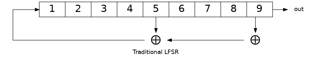
The PRBS uses the ITU standard PRBS9 polynomial \(x^{9}+x^{5}+1\)
This is the traditional form for a linear feedback shift register (LFSR) used to generate a psuedorandom binary sequence.
However, the M17 LFSR is a slightly different. The M17 PRBS9 uses the generated bit as the output bit rather than the high-bit before the shift.
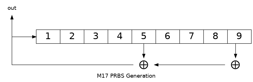
This will result in the same sequence, just shifted by nine bits.
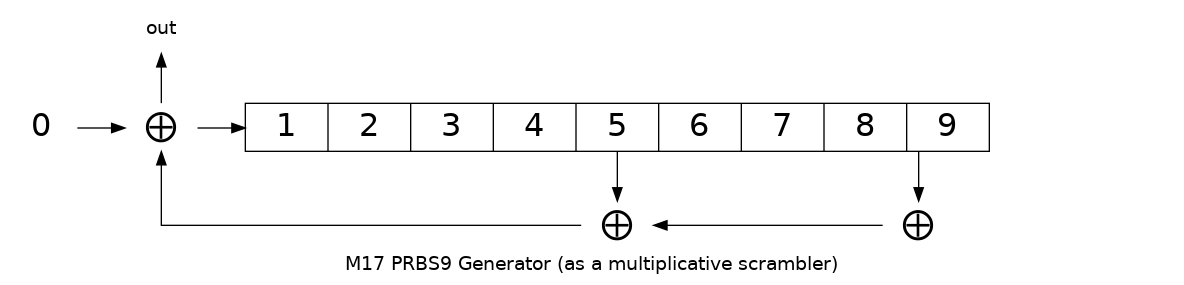
The reason for this is that it allows for easier synchronization. This is equivalent to a multiplicative scrambler (a self-synchronizing scrambler) fed with a stream of 0s.
class PRBS9 {
  static constexpr uint16_t MASK = 0x1FF;
  static constexpr uint8_t TAP_1 = 8;             // Bit 9
  static constexpr uint8_t TAP_2 = 4;             // Bit 5

  uint16_t state = 1;

public:
  bool generate()
  {
      bool result = ((state >> TAP_1) ^ (state >> TAP_2)) & 1;
      state = ((state << 1) | result) & MASK;
      return result;
  }
  ...
};
The PRBS9 SHOULD be initialized with a state of 1.
| Bits | Meaning |
|---|---|
| 0-196 | BERT PRBS9 payload |
| 4 | Flush bits for convolutional coder |
The 201 bits are convolutionally encoded to 402 type 2 bits.
The 402 bits are punctured using the P2 puncture matrix to get 368 type 3 bits.
The 368 punctured bits are interleaved and decorrelated to get the type 4 bits to be transmitted.
This provides the same error correction coding used for the stream payload.
| Bits | Meaning |
|---|---|
| 16 bits | Sync word 0xDF55 |
| 368 bits | Payload |
BERT Receiver
The receiver detects the frame is a BERT frame based on the sync word received. If the PRBS9 generator is reset at this point, the sender and receiver should be synchonized at the start. This, however, is not common nor is it required. PRBS generators can be self-synchronizing.
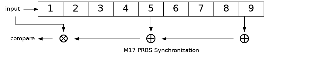
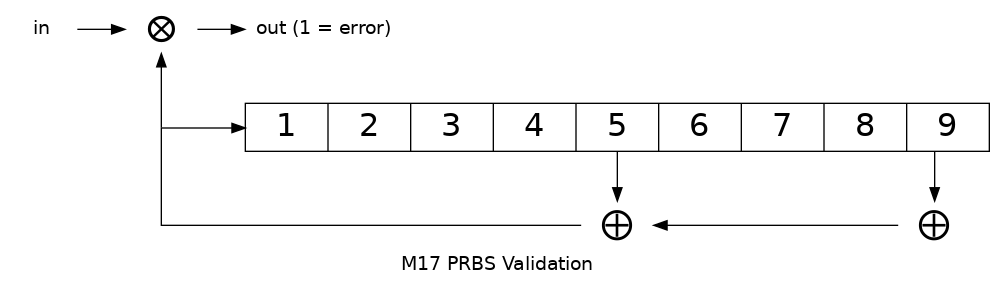
Synchronization
The receiver will synchronize the PRBS by first XORing the received bit with the LFSR taps. If the result of the XOR is a 1, it is an error (the expected feedback bit and the input do not match) and the sync count is reset. The received bit is then also shifted into the LFSR state register. Once a sequence of eighteen (18) consecutive good bits are recovered (twice the length of the LFSR), the stream is considered syncronized.
During synchronization, bits received and bit errors are not counted towards the overall bit error rate.
class PRBS9 {
  ...
  static constexpr uint8_t LOCK_COUNT = 18;   // 18 consecutive good bits.
  ...
  // PRBS Syncronizer. Returns 0 if the bit matches the PRBS, otherwise 1.
  // When synchronizing the LFSR used in the PRBS, a single bad input bit
  // will result in 3 error bits being emitted, one for each tap in the LFSR.
  bool syncronize(bool bit)
  {
      bool result = (bit ^ (state >> TAP_1) ^ (state >> TAP_2)) & 1;
      state = ((state << 1) | bit) & MASK;
      if (result) {
          sync_count = 0; // error
      } else {
          if (++sync_count == LOCK_COUNT) {
              synced = true;
              ...
          }
      }
      return result;
  }
  ...
};
Counting Bit Errors
After synchronization, BERT mode switchs to error-counting mode, where the received bits are compared to a free-running PRBS9 generator. Each bit that does not match the output of the free-running LFSR is counted as a bit error.
class PRBS9 {
  ...
  // PRBS validator.  Returns 0 if the bit matches the PRBS, otherwise 1.
  // The results are only valid when sync() returns true;
  bool validate(bool bit)
  {
      bool result;
      if (!synced) {
          result = synchronize(bit);
      } else {
          // PRBS is now free-running.
          result = bit ^ generate();
          count_errors(result);
      }
      return result;
  }
  ...
};
Resynchronization
The receiver must keep track of the number of bit errors over a period of 128 bits. If more than 18 bit errors occur, the synchronization process starts anew. This is necessary in the case of missed frames or other serious synchronization issues.
Bits received and errors which occur during resynchronization are not counted towards the bit error rate.